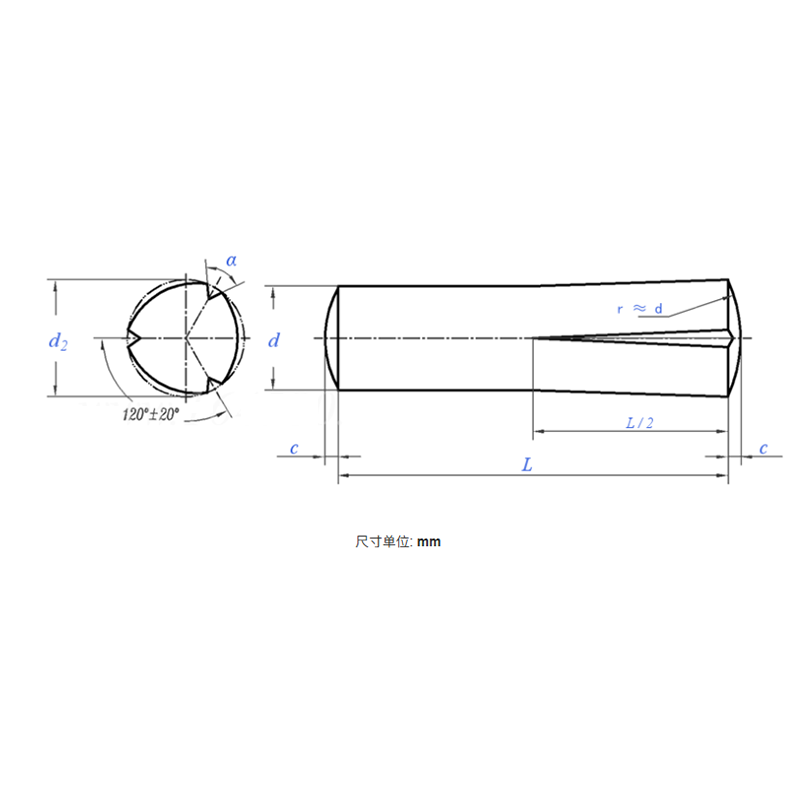
Product Specifications
| Model / Specification | M1.5–M25 |
| Material | Stainless Steel |
| Nom. Dia. d |
Φ1.5 | Φ2 | Φ2.5 | Φ3 | Φ4 | Φ5 | Φ6 | Φ8 | Φ10 | Φ12 | Φ14 | Φ16 | Φ20 | Φ25 | |
| d | Max. | 1.5 | 2 | 2.5 | 3 | 4 | 5 | 6 | 8 | 10 | 12 | 14 | 16 | 18 | 20 |
| Min. | 1.475 | 1.975 | 2.475 | 2.975 | 3.925 | 4.925 | 5.925 | 7.91 | 9.91 | 11.89 | 13.89 | 15.89 | 19.87 | 24.87 | |
| c | Nom. Dia. | 0.2 | 0.25 | 0.3 | 0.4 | 0.5 | 0.6 | 0.8 | 1 | 1.2 | 1.6 | 1.6 | 2 | 2.5 | 3 |
| α | ±3° | 70° | 70° | 70° | 70° | 70° | 70° | 70° | 70° | 70° | 70° | 70° | 70° | 70° | 70° |
| Min. Shear (Double), kN | 1.60 | 2.85 | 4.25 | 6.15 | 10.6 | 16.5 | 22.8 | 40.5 | 63.2 | 91.0 | 124 | 156.8 | 236.5 | 370.1 | |
| d2 | - | - | - | - | - | - | - | - | - | - | - | - | - | - | |
| Weight/1000 pcs (Steel) ≈ kg | - | - | - | - | - | - | - | - | - | - | - | - | - | - | |
Slotted Spring Pin (Half Length Conical Groove) — PRODUCT INTRODUCTION
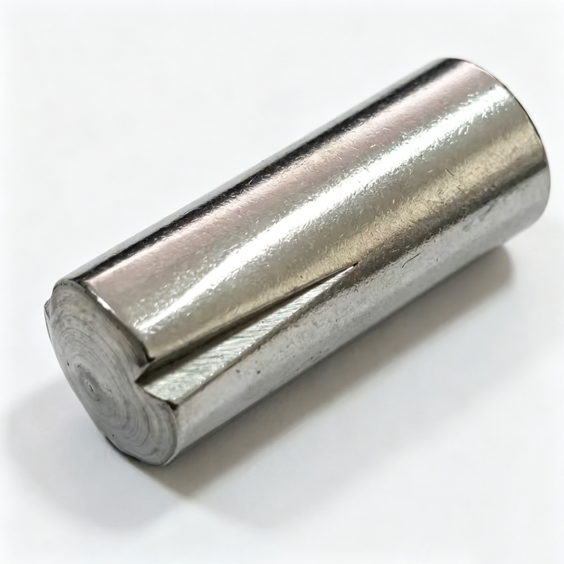
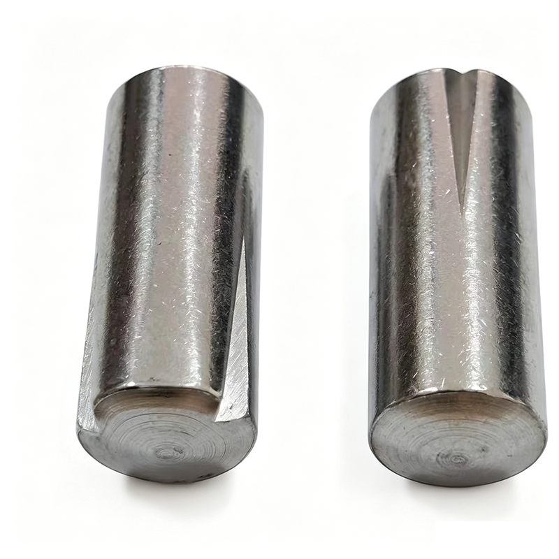
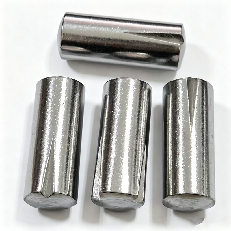
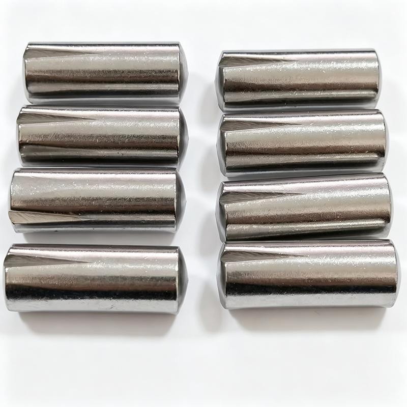
The half length conical groove slotted spring pin is an elastic locking pin manufactured on a cylindrical pin body, with three grooves rolled axially from one end, gradually tapering and shallowing toward the middle — covering approximately half the pin length. The slotted end is press-fitted into the hole to create an interference fit for locking, while the smooth half acts as a guide or locator. Combining both locking and positioning functions in one pin, assembly requires only drilling a straight hole — no reaming, tapping, or snap ring installation needed.
I. PRODUCT FEATURES
Half Length Conical Groove Structure: Three grooves taper from the tip toward the center and gradually disappear, with only the slotted half producing an expansion force while the other half presents a smooth cylindrical surface.
Elastic Interference Fit Principle: The raised metal at the slotted sections forms reliable three-line contact with the hole wall, providing radial locking force with excellent resistance to vibration and loosening.
Separated Locking and Guiding Functions: The slotted half handles locking while the smooth half serves as a positioning pin or guide rod — one pin, two functions.
Material and Hardness: Standard options include carbon steel (hardened to HRC 45–56) or austenitic stainless steel (A2), with surface treatment available in black oxide, phosphating, or zinc plating.
II. PRODUCT ADVANTAGES
Extremely Simple Assembly: Only a straight hole needs to be drilled; the pin is driven in with a hammer or press. No tapered reaming, tapping, or snap ring installation required, significantly reducing assembly costs.
Tolerates Hole Variation: The elastic groove structure absorbs a certain range of hole size deviations, lowering drilling precision requirements with minimal scrap rate.
Repeatedly Installable and Removable: Can be assembled and disassembled multiple times without significant loss of locking force, facilitating equipment maintenance and part replacement.
Non-Damaging to Hole Walls: The elastic expansion force is evenly distributed; compared to solid cylindrical pins, it causes less damage to hole walls, making it suitable for softer base materials.
III. APPLICATION AREAS
Power Transmission and Hub Connections: Secures gears, pulleys, and levers onto shafts, with the smooth section serving as bearing seats or spacer positioning.
Handle and Handwheel Assemblies: Elastic fixing of handle shafts to ball ends or control levers to connection sleeves; the smooth section provides a comfortable grip surface.
Hinges and Movable Joints: Serving as hinged shafts in agricultural machinery and furniture hardware to provide vibration-resistant movable connections.
Fixtures and Molds: Positioning templates and drill bushings, utilizing the smooth section for guidance and the grooved section for locking.
Small Motors and Automotive Components: Simple and reliable fixing in applications such as wiper linkages, seat adjustment mechanisms, and door lock assemblies.