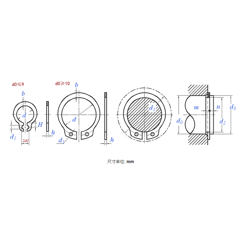
Product Specifications
| Model / Specification | M3–M200 |
| Material | Stainless Steel |
| Shaft Dia. d0 |
3 | 4 | 5 | 6 | 7 | 8 | 9 | 10 | 11 | 12 | 13 | 14 | 15 | 16 | 17 | 18 | |
| d | Nom. | 2.7 | 3.7 | 4.7 | 5.6 | 6.5 | 7.4 | 8.4 | 9.3 | 10.2 | 11 | 11.9 | 12.9 | 13.8 | 14.7 | 15.7 | 16.5 |
| Max. | 2.74 | 3.74 | 4.74 | 5.64 | 6.56 | 7.46 | 8.46 | 9.4 | 10.3 | 11.1 | 12 | 13 | 13.9 | 14.8 | 15.8 | 16.6 | |
| Min. | 2.55 | 3.55 | 4.55 | 5.45 | 6.32 | 7.22 | 8.22 | 8.94 | 9.84 | 10.64 | 11.54 | 12.54 | 13.44 | 14.34 | 15.34 | 16.14 | |
| h | Nom. | 0.4 | 0.4 | 0.6 | 0.6 | 0.6 | 0.8 | 0.8 | 1 | 1 | 1 | 1 | 1 | 1 | 1 | 1 | 1 |
| Max. | 0.43 | 0.43 | 0.64 | 0.64 | 0.64 | 0.84 | 0.84 | 1.05 | 1.05 | 1.05 | 1.05 | 1.05 | 1.05 | 1.05 | 1.05 | 1.05 | |
| Min. | 0.34 | 0.34 | 0.53 | 0.53 | 0.53 | 0.7 | 0.7 | 0.87 | 0.87 | 0.87 | 0.87 | 0.87 | 0.87 | 0.87 | 0.87 | 0.87 | |
| b | ≈ | 0.8 | 0.88 | 1.12 | 1.32 | 1.32 | 1.32 | 1.44 | 1.44 | 1.52 | 1.72 | 1.88 | 1.88 | 2 | 2.32 | 2.48 | 2.48 |
| d1 | 1 | 1 | 1 | 1.2 | 1.2 | 1.2 | 1.2 | 1.5 | 1.5 | 1.5 | 1.7 | 1.7 | 1.7 | 1.7 | 1.7 | 1.7 | |
| H | 0.95 | 1.1 | 1.25 | 1.35 | 1.55 | 1.6 | 1.65 | - | - | - | - | - | - | - | - | - | |
| d2 | Max. | 2.8 | 3.8 | 4.8 | 5.7 | 6.7 | 7.6 | 8.6 | 9.6 | 10.5 | 11.5 | 12.4 | 13.4 | 14.3 | 15.2 | 16.2 | 17 |
| Min. | 2.76 | 3.752 | 4.752 | 5.652 | 6.642 | 7.542 | 8.542 | 9.542 | 10.39 | 11.39 | 12.29 | 13.29 | 14.19 | 15.09 | 16.09 | 16.89 | |
| m | Max. | 0.64 | 0.64 | 0.84 | 0.84 | 0.84 | 1.04 | 1.04 | 1.24 | 1.24 | 1.24 | 1.24 | 1.24 | 1.24 | 1.24 | 1.24 | 1.24 |
| Min. | 0.5 | 0.5 | 0.7 | 0.7 | 0.7 | 0.9 | 0.9 | 1.1 | 1.1 | 1.1 | 1.1 | 1.1 | 1.1 | 1.1 | 1.1 | 1.1 | |
| n | ≥ | 0.3 | 0.3 | 0.3 | 0.5 | 0.5 | 0.6 | 0.6 | 0.6 | 0.8 | 0.8 | 0.9 | 0.9 | 1.1 | 1.2 | 1.2 | 1.5 |
| d3 ② | ≥ | 7.2 | 8.8 | 10.7 | 12.2 | 13.8 | 15.2 | 16.4 | 17.6 | 18.6 | 19.6 | 20.8 | 22 | 23.2 | 24.4 | 25.6 | 27 |
| Weight/1000 pcs (Steel) ≈ kg | 0.02 | 0.03 | 0.08 | 0.11 | 0.12 | 0.19 | 0.22 | 0.24 | 0.28 | 0.35 | 0.41 | 0.44 | 0.51 | 0.65 | 0.74 | 0.78 | |
| Shaft Dia. d0 |
140 | 145 | 150 | 155 | 160 | 165 | 170 | 175 | 180 | 185 | 190 | 195 | 200 | |
| d | Nom. | 133 | 138 | 142 | 146 | 151 | 155.5 | 160.5 | 165.5 | 170.5 | 175.5 | 180.5 | 185.5 | 190.5 |
| Max. | 133.63 | 138.63 | 142.63 | 146.63 | 151.63 | 156.13 | 161.13 | 166.13 | 171.13 | 176.13 | 181.22 | 186.22 | 191.22 | |
| Min. | 131.5 | 136.5 | 140.5 | 144.5 | 149.5 | 154 | 159 | 164 | 169 | 174 | 178.8 | 183.8 | 188.8 | |
| h | Nom. | 3 | 3 | 3 | 3 | 3 | 3 | 3 | 3 | 3 | 3 | 3 | 3 | 3 |
| Max. | 3.07 | 3.07 | 3.07 | 3.07 | 3.07 | 3.07 | 3.07 | 3.07 | 3.07 | 3.07 | 3.07 | 3.07 | 3.07 | |
| Min. | 2.78 | 2.78 | 2.78 | 2.78 | 2.78 | 2.78 | 2.78 | 2.78 | 2.78 | 2.78 | 2.78 | 2.78 | 2.78 | |
| b | ≈ | 13.2 | 13.2 | 14 | 14 | 14 | 14.4 | 14.4 | 15 | 15 | 15.2 | 15.2 | 15.6 | 15.6 |
| d1 | 4 | 4 | 4 | 4 | 4 | 4 | 4 | 4 | 4 | 4 | 4 | 4 | 4 | |
| H | - | - | - | - | - | - | - | - | - | - | - | - | - | |
| d2 | Max. | 136 | 141 | 145 | 150 | 155 | 160 | 165 | 170 | 175 | 180 | 185 | 190 | 195 |
| Min. | 135.37 | 140.37 | 144.37 | 149.37 | 154.37 | 159.37 | 164.37 | 169.37 | 174.37 | 179.37 | 184.28 | 189.28 | 194.28 | |
| m | Max. | 3.38 | 3.38 | 3.38 | 3.38 | 3.38 | 3.38 | 3.38 | 3.38 | 3.38 | 3.38 | 3.38 | 3.38 | 3.38 |
| Min. | 3.2 | 3.2 | 3.2 | 3.2 | 3.2 | 3.2 | 3.2 | 3.2 | 3.2 | 3.2 | 3.2 | 3.2 | 3.2 | |
| n | ≥ | 6 | 6 | 7.5 | 7.5 | 7.5 | 7.5 | 7.5 | 7.5 | 7.5 | 7.5 | 7.5 | 7.5 | 7.5 |
| d3 ② | ≥ | 168 | 174.4 | 180 | 186 | 190 | 195 | 200 | 206 | 212 | 218 | 223 | 229 | 235 |
| Weight/1000 pcs (Steel) ≈ kg | 104.4 | 108.3 | 111.2 | 120.2 | 124.1 | 131.4 | 134.7 | 142.1 | 149.7 | 156 | 160.2 | 169.8 | 174.1 | |
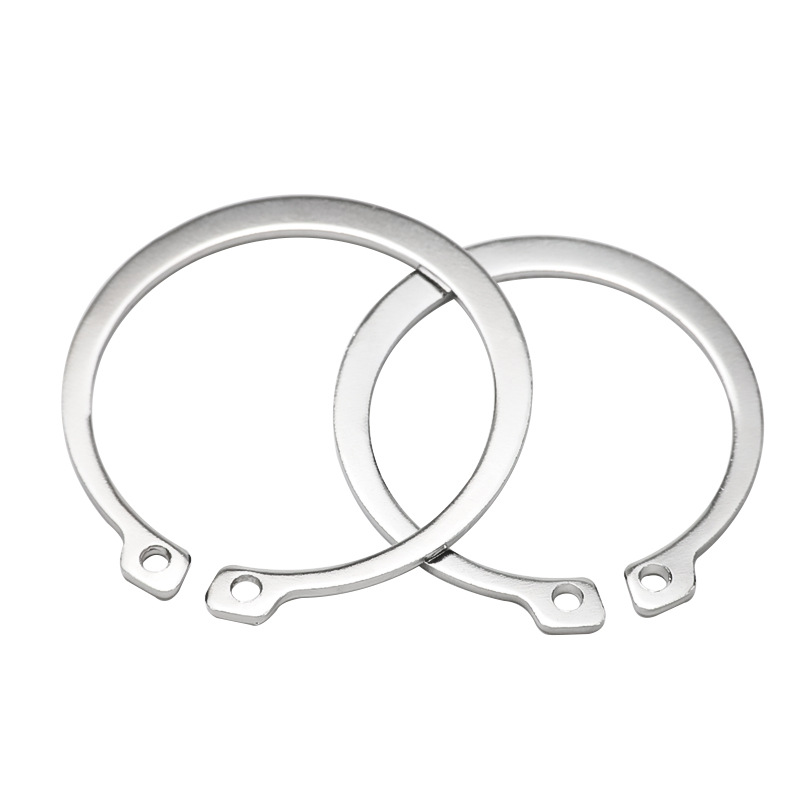
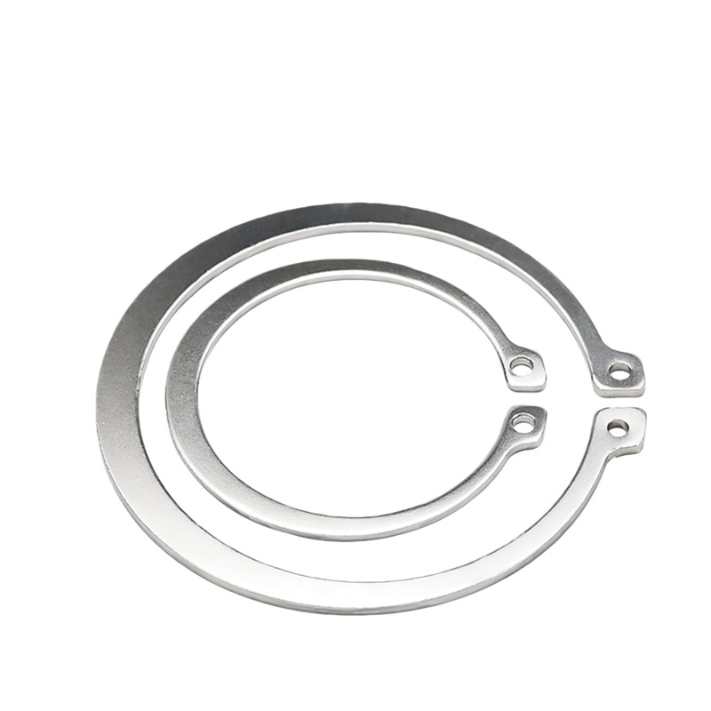
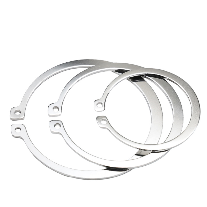
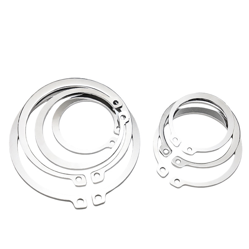
AXIAL ELASTIC RETAINING RING — TYPE A PRODUCT INTRODUCTION
The Type A Axial Elastic Retaining Ring is a standardized fastener designed to be installed in a groove on a shaft, primarily used to limit the axial displacement of shaft components such as bearings, gears, and pulleys. Manufactured from spring steel or stainless steel via stamping and coiling, it achieves clamping and removal through elastic deformation of its open-ended structure. With a simple design and easy installation, it is widely used across various mechanical transmission and assembly structures.
I. PRODUCT FEATURES
Standardized Open-End Design: Type A is the standard version, featuring a process hole (plier hole) at the open end for disassembly, enabling quick installation and removal with snap ring pliers.
Excellent Elasticity and Retention Force: Made from spring steel with strict heat treatment, it can be repeatedly installed and removed within its elastic limit without permanent deformation, providing stable axial locking force.
Compact, Thin-Section Structure: With minimal thickness, the retaining ring occupies virtually no additional axial space, making it especially suitable for applications with high space constraints.
Multiple Material Options: Standard applications use 65Mn or 60Si2MnA; high-fatigue conditions use 50CrVA; corrosion-resistant applications use 06Cr19Ni10 (304) or 06Cr17Ni12Mo2 (316) — adapting to different working environments.
II. PRODUCT ADVANTAGES
Efficient Installation and Removal: Paired with snap ring pliers, it can be quickly installed and removed without special tools, significantly improving assembly and maintenance efficiency.
Reliable Positioning Without Shaft Damage: Once seated in the dedicated groove, the retaining ring forms a rigid axial stop. Its small contact area with the shaft prevents scratching of mating surfaces.
Excellent Cost Performance: With a simple structure and low manufacturing cost, it is a highly cost-effective axial positioning solution and is also very easy to replace.
Suitable for High Speed and Vibration: High-strength spring steel can withstand elevated rotational speeds and light vibrations, maintaining its clamping state even during high-speed operation.
III. APPLICATIONS
Automotive and Motorcycles: Axial stops for transmission shafts, steering knuckles, rocker arm shafts, shock absorber piston rods, and similar components.
Mechanical, Electrical, and Power Tools: Axial locking of bearings and gears in rotating machinery such as electric motors, generators, and angle grinders.
Household Appliances and Office Equipment: Simple and reliable positioning in washing machines, air conditioner compressors, printer rollers, and similar assemblies.
Industrial Transmission and Hydraulics/Pneumatics: Axial positioning of components in reducers, hydraulic cylinder piston rods, cylinder fittings, valve shafts, and similar parts.
Agriculture and Construction Machinery: Connections in vibrating and dusty environments such as mower blade shafts, small engine crankshafts, and transport wheel shafts.