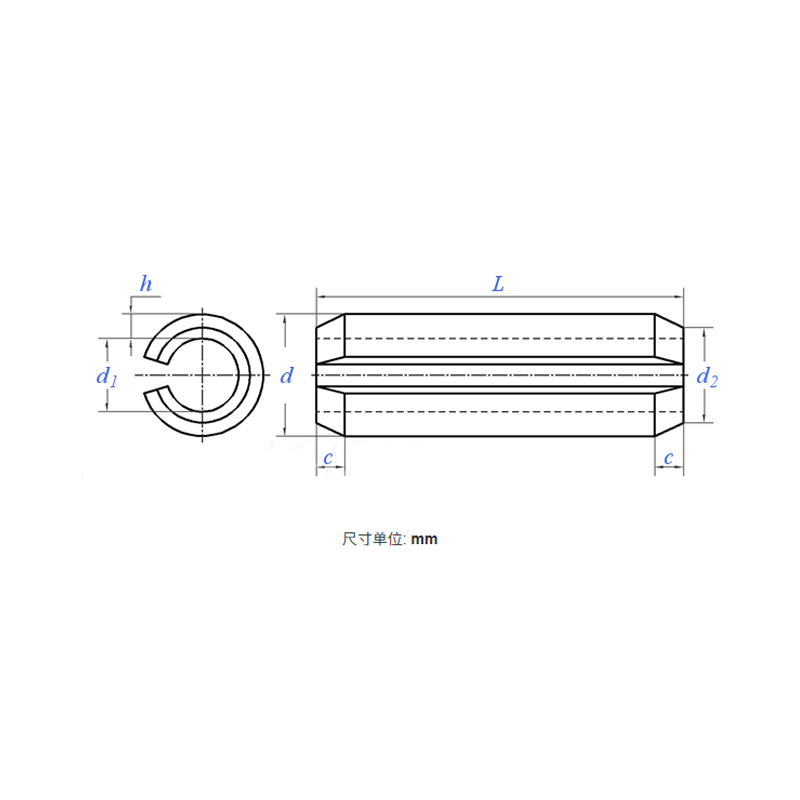
Product Specifications
| Model / Specification | M1–M50 |
| Material | Stainless Steel |
| Nom. Dia. d |
1 | 1.5 | 2 | 2.5 | 3 | 3.5 | 4 | 4.5 | 5 | 6 | 8 | 10 | 12 | 13 | ||
| d | Before Installation | Max. | 1.3 | 1.8 | 2.4 | 2.9 | 3.5 | 4.0 | 4.6 | 5.1 | 5.6 | 6.7 | 8.8 | 10.8 | 12.8 | 13.8 |
| Min. | 1.2 | 1.7 | 2.3 | 2.8 | 3.3 | 3.8 | 4.4 | 4.9 | 5.4 | 6.4 | 8.5 | 10.5 | 12.5 | 13.5 | ||
| d1 | Before Installation | Ref. | 0.8 | 1.1 | 1.5 | 1.8 | 2.1 | 2.3 | 2.8 | 2.9 | 3.4 | 4 | 5.5 | 6.5 | 7.5 | 8.5 |
| c | Max. | 0.35 | 0.45 | 0.55 | 0.6 | 0.7 | 0.8 | 0.85 | 1 | 1.1 | 1.4 | 2 | 2.4 | 2.4 | 2.4 | |
| Min. | 0.15 | 0.25 | 0.35 | 0.4 | 0.5 | 0.6 | 0.65 | 0.8 | 0.9 | 1.2 | 1.6 | 2 | 2 | 2 | ||
| h | 0.2 | 0.3 | 0.4 | 0.5 | 0.6 | 0.75 | 0.8 | 1 | 1 | 1.2 | 1.5 | 2 | 2.5 | 2.5 | ||
| Min. Shear Load, Double, kN | 0.7 | 0.15 | 2.82 | 4.38 | 6.32 | 9.06 | 11.24 | 15.36 | 17.54 | 26.04 | 42.76 | 70.16 | 104.1 | 115.1 | ||
| Wt./1000 Pcs (Steel) ≈ kg | - | - | - | - | - | - | - | - | - | - | - | - | - | - | ||
| Nom. Dia. d |
14 | 16 | 18 | 20 | 21 | 25 | 28 | 30 | 32 | 35 | 38 | 40 | 45 | 50 | ||
| d | Before Installation | Max. | 14.8 | 16.8 | 18.9 | 20.9 | 21.9 | 25.9 | 28.9 | 30.9 | 32.9 | 32.9 | 38.9 | 40.9 | 45.9 | 50.9 |
| Min. | 14.5 | 16.5 | 18.5 | 20.5 | 21.5 | 25.5 | 28.5 | 30.5 | 32.5 | 32.5 | 38.5 | 40.5 | 45.5 | 50.5 | ||
| d1 | Before Installation | Ref. | 8.5 | 10.5 | 11.5 | 12.5 | 13.5 | 15.5 | 17.5 | 18.5 | 20.5 | 21.5 | 23.5 | 25.5 | 28.5 | 31.5 |
| c | Max. | 2.4 | 2.4 | 2.4 | 3.4 | 3.4 | 3.4 | 3.4 | 3.4 | 3.6 | 3.6 | 4.6 | 4.6 | 4.6 | 4.6 | |
| Min. | 2 | 2 | 2 | 3 | 3 | 3 | 3 | 3 | 3 | 3 | 4 | 4 | 4 | 4 | ||
| h | 3 | 3 | 3.5 | 4 | 4 | 5 | 5.5 | 6 | 6 | 7 | 7.5 | 7.5 | 8.5 | 9.5 | ||
| Min. Shear Load, Double, kN | 144.7 | 171 | 222.5 | 280.6 | 298.2 | 438.5 | 542.6 | 631.4 | 684 | 859 | 1003 | 1068 | 1360 | 1685 | ||
| Wt./1000 Pcs (Steel) ≈ kg | - | - | - | - | - | - | - | - | - | - | - | - | - | - | ||
ELASTIC CYLINDRICAL PIN — PRODUCT INTRODUCTION
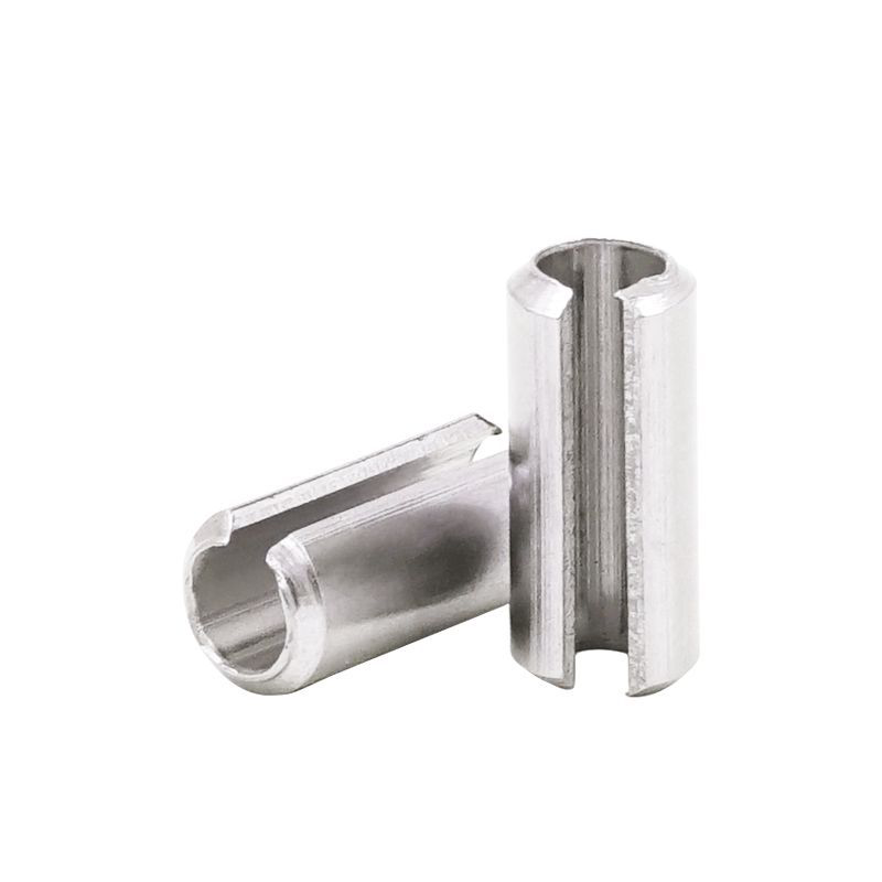
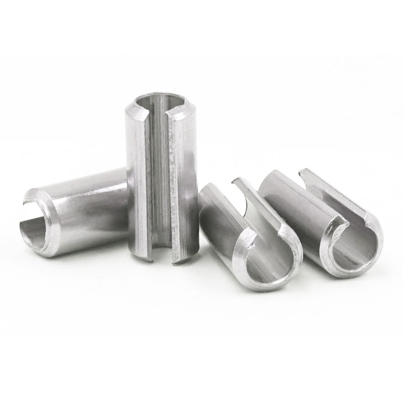
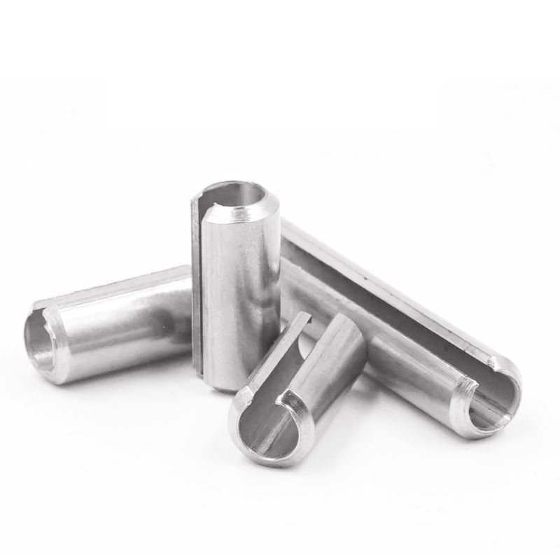
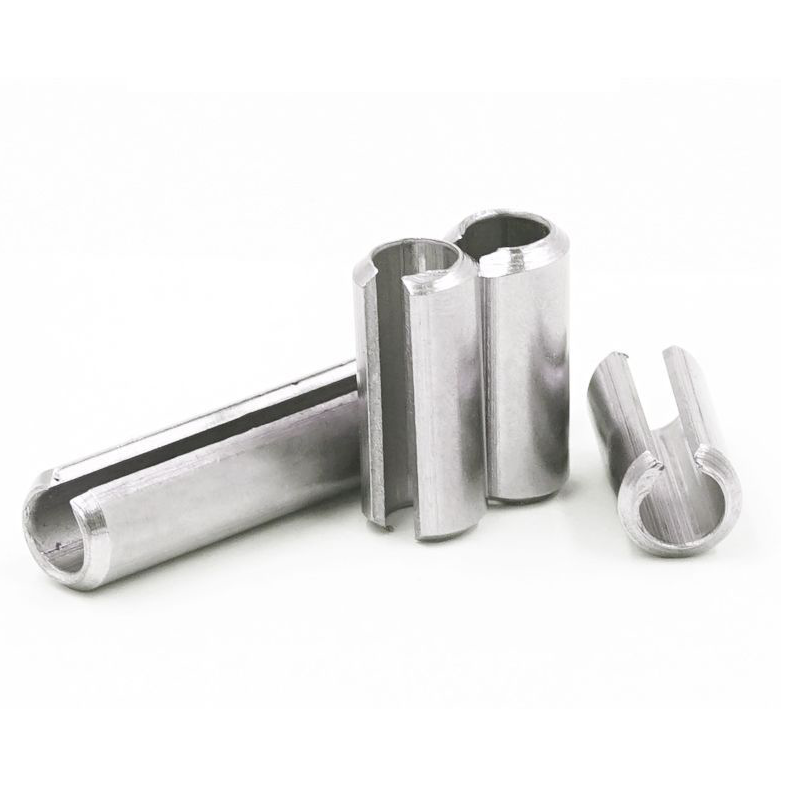
The spring pin is a hollow fastener made by coiling spring steel or stainless steel strip, available in two types: straight slotted and spiral wound. During installation, it is driven into a pin hole, where its radial tension generated by its own elasticity creates a tight interference fit with the hole wall, achieving component connection, positioning, or shear resistance. Its hollow structure effectively absorbs vibration and impact while protecting the hole wall from damage.
Our spring pins are manufactured in strict accordance with national standards (GB/T 879.1–879.4), international standards (ISO 8752/13337), and German standards (DIN 1481), covering materials such as 65Mn/60Si2Mn spring steel and A2/A4 stainless steel. They are widely used as alternatives to standard solid dowel pins, especially in applications involving vibration, impact, and situations where hole wall protection is required.
I. PRODUCT FEATURES
Elastic radial expansion design:
With built-in radial elasticity, the pin generates continuous radial tension after insertion into the hole, effectively absorbing vibration and shock, preventing loosening from the very start.
Hollow thin-wall construction:
Upon shear loading, the pin first undergoes elastic deformation, buffering instantaneous loads and protecting thin-walled components or light alloy hole walls from damage.
Multiple coil configurations:
- Slotted Type (GB/T 879.1): Straight slotted, highly versatile, high radial rigidity.
- Light Duty Type (GB/T 879.2): Thin wall, low insertion force, suitable for light loads and precision fits.
- Spiral Wound Type (GB/T 879.4): Formed from 2.25 turns of steel strip, uniform elasticity, excellent shear strength and toughness.
Optional lead-in chamfer:
Spiral wound spring pins can be manufactured with one or both ends chamfered, facilitating smooth insertion during automated assembly.
II. PRODUCT ADVANTAGES
Outstanding loosening resistance and vibration dampening:
Secured by its own expansion pressure, the pin has no protruding parts requiring bending like cotter pins, and unlike solid dowel pins, it will not loosen due to hole wall wear.
Low installation hole processing cost:
Because the pin itself is compressible, pin hole tolerance requirements are generous — no reaming is needed, ordinary drilling is sufficient, significantly reducing manufacturing costs.
Reusable:
As long as straight slotted or spiral wound spring pins remain within their elastic limit after removal, they can be reused multiple times without losing their expansion pressure.
Simple and safe assembly:
No special tools are required — simply drive the pin in. With no sharp open ends, the pin is safe to handle and presents a neat, flush appearance.
III. AREAS OF APPLICATION
Automotive and construction machinery:
Used at connection points requiring continuous vibration resistance, such as door hinges, brake pedals, steering columns, and seat adjustment mechanisms.
Power and transmission systems:
Coupler pins in motors and pump equipment; circumferential fastening of gears and shafts.
Tooling, jigs, and molds:
Positioning and guidance in stamping dies and injection molds, enabling quick changeovers.
General machinery and electronics:
Hinge and linkage connections in printers, fitness equipment, bicycles, and electronic cabinets — particularly suitable for die-cast aluminum, plastic, and other substrates unsuited to interference fits.