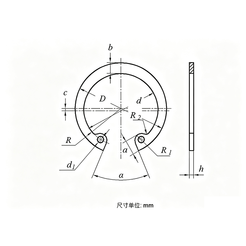
Product Specifications
| Model / Specification | M8–M200 |
| Material | Stainless Steel |
| Bore Dia. d0 |
8 | 9 | 10 | 11 | 12 | 13 | 14 | 15 | 16 | 17 | 18 | 19 | 20 | 21 | 22 | 24 | |
| D | Nom. | 8.7 | 9.8 | 10.8 | 11.8 | 13 | 14.1 | 15.1 | 16.2 | 17.3 | 18.3 | 19.5 | 20.5 | 21.5 | 22.5 | 23.5 | 25.9 |
| Min. | 8.6 | 9.7 | 10.7 | 11.7 | 12.9 | 14 | 15 | 16.1 | 17.2 | 18.17 | 19.37 | 20.37 | 21.37 | 22.37 | 23.37 | 25.69 | |
| Max. | 9.06 | 10.16 | 11.16 | 12.16 | 13.36 | 14.46 | 15.46 | 16.56 | 17.66 | 18.72 | 19.92 | 20.92 | 21.92 | 22.92 | 23.92 | 26.32 | |
| h | Nom. | 0.6 | 0.6 | 0.8 | 0.8 | 0.8 | 0.8 | 1 | 1 | 1 | 1 | 1 | 1 | 1 | 1 | 1 | 1.2 |
| Min. | 0.53 | 0.53 | 0.7 | 0.7 | 0.7 | 0.7 | 0.87 | 0.87 | 0.87 | 0.87 | 0.87 | 0.87 | 0.87 | 0.87 | 0.87 | 1.07 | |
| Max. | 0.64 | 0.64 | 0.84 | 0.84 | 0.84 | 0.84 | 1.05 | 1.05 | 1.05 | 1.05 | 1.05 | 1.05 | 1.05 | 1.05 | 1.05 | 1.25 | |
| d1 | 1 | 1 | 1.5 | 1.5 | 1.5 | 1.7 | 1.7 | 1.7 | 1.7 | 1.7 | 1.7 | 2 | 2 | 2 | 2 | 2 | |
| α | 45° | 45° | 45° | 45° | 45° | 45° | 45° | 45° | 45° | 45° | 45° | 45° | 45° | 45° | 45° | 45° | |
| c | Min. = Nom. | 0.3 | 0.3 | 0.4 | 0.4 | 0.4 | 0.4 | 0.5 | 0.5 | 0.5 | 0.5 | 0.5 | 0.6 | 0.6 | 0.6 | 0.6 | 0.6 |
| Max. | 0.335 | 0.335 | 0.44 | 0.44 | 0.44 | 0.44 | 0.54 | 0.54 | 0.54 | 0.54 | 0.54 | 0.64 | 0.64 | 0.64 | 0.64 | 0.64 | |
| a | Max. | 2.33 | 2.48 | 2.98 | 2.98 | 3.08 | 3.43 | 3.43 | 3.48 | 3.53 | 3.56 | 3.76 | 4.26 | 4.26 | 4.26 | 4.26 | 4.36 |
| R | 3.2 | 3.6 | 4.1 | 4.6 | 5.1 | 5.5 | 6 | 6.5 | 7 | 7.5 | 7.9 | 8.2 | 8.7 | 9.2 | 9.7 | 10.8 | |
| R1 | 1 | 1 | 1.5 | 1.5 | 1.5 | 1.7 | 1.7 | 1.7 | 1.7 | 1.7 | 1.7 | 2 | 2 | 2 | 2 | 2 | |
| R2 | 0.8 | 0.8 | 1 | 1 | 1 | 1 | 1 | 1 | 1 | 1 | 1 | 1.2 | 1.2 | 1.2 | 1.2 | 1.2 | |
| b | ≈ | 1 | 1.2 | 1.7 | 1.7 | 1.7 | 1.7 | 2.1 | 2.1 | 2.1 | 2.1 | 2.1 | 2.5 | 2.5 | 2.5 | 2.5 | 2.5 |
| Wt/1000 Pcs (Steel) ≈ kg | 0.09 | 0.1 | 0.23 | 0.26 | 0.28 | 0.31 | 0.5 | 0.54 | 0.57 | 0.61 | 0.64 | 0.8 | 0.84 | 0.88 | 0.92 | 1.21 | |
| Bore Dia. d0 |
135 | 140 | 145 | 150 | 155 | 160 | 165 | 170 | 175 | 180 | 185 | 190 | 195 | 200 | |
| D | Nom. | 142 | 147 | 152 | 158 | 164 | 169 | 174.5 | 179.5 | 184.5 | 189.5 | 194.5 | 199.5 | 204.5 | 209.5 |
| Min. | 141.37 | 146.37 | 151.37 | 157.37 | 163.37 | 168.37 | 173.87 | 178.87 | 183.78 | 188.78 | 193.78 | 198.78 | 203.78 | 208.78 | |
| Max. | 143.5 | 148.5 | 153.5 | 159.5 | 165.5 | 170.5 | 176 | 181 | 186.2 | 191.2 | 196.2 | 201.2 | 206.2 | 211.2 | |
| h | Nom. | 3 | 3 | 3 | 3 | 3 | 3 | 3 | 3 | 3 | 3 | 3 | 3 | 3 | 3 |
| Min. | 2.78 | 2.78 | 2.78 | 2.78 | 2.78 | 2.78 | 2.78 | 2.78 | 2.78 | 2.78 | 2.78 | 2.78 | 2.78 | 2.78 | |
| Max. | 3.07 | 3.07 | 3.07 | 3.07 | 3.07 | 3.07 | 3.07 | 3.07 | 3.07 | 3.07 | 3.07 | 3.07 | 3.07 | 3.07 | |
| d1 | 4 | 4 | 4 | 4 | 4 | 4 | 4 | 4 | 4 | 4 | 4 | 4 | 4 | 4 | |
| α | 30° | 30° | 30° | 30° | 30° | 30° | 30° | 30° | 30° | 30° | 30° | 30° | 30° | 30° | |
| c | Min. = Nom. | 2.7 | 2.7 | 2.75 | 2.8 | 2.9 | 2.9 | 2.95 | 3.1 | 3.2 | 3.2 | 3.3 | 3.3 | 3.3 | 3.3 |
| Max. | 2.76 | 2.76 | 2.81 | 2.86 | 2.96 | 2.96 | 3.01 | 3.16 | 3.26 | 3.26 | 3.36 | 3.36 | 3.36 | 3.36 | |
| a | Max. | 11.45 | 11.45 | 12.45 | 12.95 | 13.45 | 13.45 | 13.5 | 13.5 | 13.6 | 14.1 | 14.1 | 14.1 | 14.1 | 14.1 |
| R | 65.3 | 67.8 | 70.3 | 72.8 | 75.3 | 77.8 | 81 | 83 | 85.5 | 87.5 | 90 | 92.5 | 95 | 97.5 | |
| R1 | 5 | 5 | 6 | 6 | 6 | 6 | 6 | 6 | 6 | 6 | 6 | 6 | 6 | 6 | |
| R2 | 2.5 | 2.5 | 3 | 3 | 3 | 3 | 3 | 3 | 3 | 3 | 3 | 3 | 3 | 3 | |
| b | ≈ | 10.7 | 10.7 | 10.9 | 10.9 | 11.6 | 11.6 | 11.8 | 12.3 | 12.7 | 12.8 | 12.9 | 13.1 | 13.1 | 13.2 |
| Wt/1000 Pcs (Steel) ≈ kg | 75.3 | 78.06 | 83.13 | 88.67 | 94.93 | 97.92 | 103.4 | 110.7 | 116.9 | 121.6 | 124.2 | 129.5 | 133.6 | 138.3 | |
HOLE-TYPE SPRING RETAINING RING (TYPE A) — PRODUCT INTRODUCTION
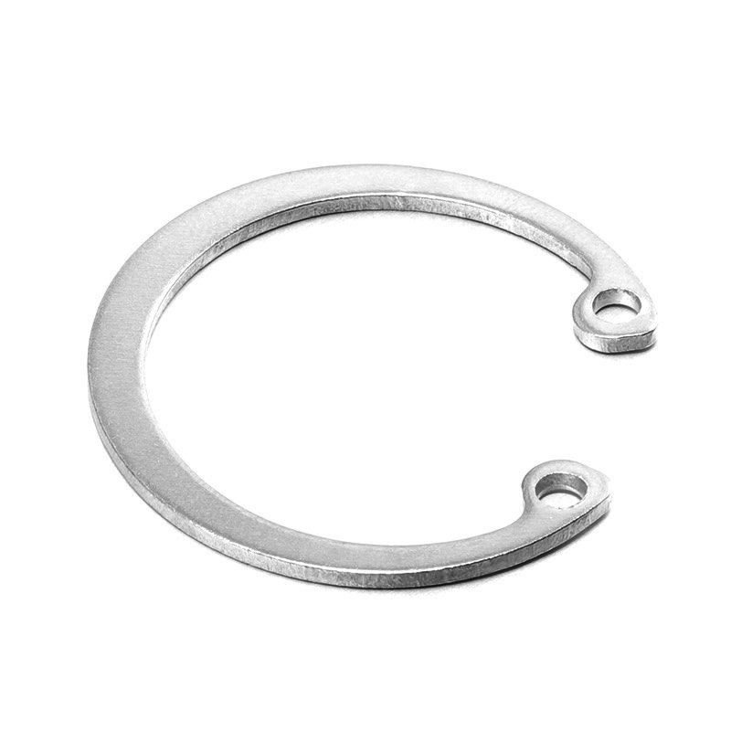
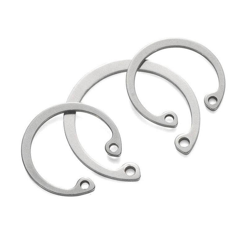
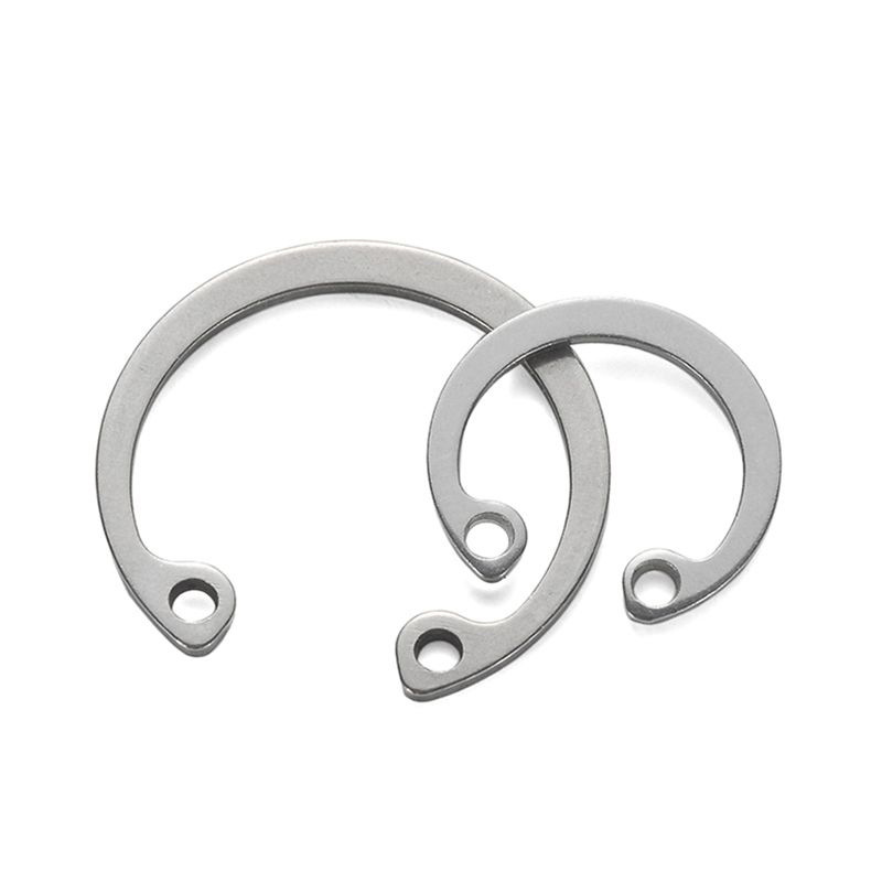
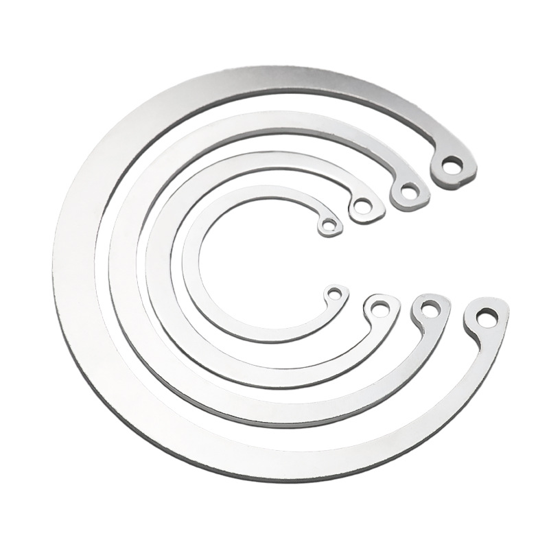
The Type A hole-type spring retaining ring is an open elastic circular ring with a rectangular cross-section and two installation plier holes. It is installed in a preset groove inside a round bore of the workpiece, relying on the material’s own elastic recovery force to tightly grip the groove. The key difference between Type A and Type B is that Type A has two installation holes located at both ends of the gap, making it more suitable for larger bore diameters. The commonly used material is 65Mn spring steel, which after heat treatment receives black oxide or phosphating treatment to maintain excellent elasticity and hardness.
I. PRODUCT FEATURES
Type A Plier Hole Structure: Two symmetrically positioned installation plier holes are designed at both ends of the gap, specifically engineered to match circlip pliers for expansion-style installation, ensuring precise positioning and uniform force distribution.
High-Strength Elasticity: The ring relies entirely on the material’s own elastic deformation for installation and removal. Made from premium spring steel such as 65Mn, with hardness stably maintained at HRC 44–52 after heat treatment, ensuring long-term elastic performance without degradation.
Standardized Interchangeability: Strictly manufactured in accordance with GB/T 893.1 standard, with precise control over cross-section thickness and bore diameter tolerances, ensuring perfect matching with standard hole-type grooves (retaining ring grooves).
Anti-Rust Surface Treatment: Standard treatment is black oxide or phosphating with an oil film for rust prevention. For wind power or demanding applications, Dacromet or mechanical zinc plating can be applied to effectively avoid hydrogen embrittlement risk and ensure safe elastic performance.
II. PRODUCT ADVANTAGES
Reliable Axial Positioning: Once installed in the groove, the retaining ring becomes a rigid axial stop for internal components, capable of withstanding substantial axial thrust without slipping like an ordinary washer.
Quick Installation and Removal: With a circlip plier, the ring allows rapid, non-damaging installation and removal, facilitating easy maintenance and replacement of internal parts such as bearings, gears, and seals, significantly reducing maintenance labor time.
Compact, Space-Saving Design: Fully embedded within the groove inside the bore, it occupies virtually no additional axial space and does not increase the equipment’s outer diameter, making it ideal for compact and lightweight internal component design.
Vibration Resistance and Anti-Loosening: Relying on elastic tension within the groove, it does not loosen or spin back due to vibration under high-speed rotation and dynamic conditions — unlike bolted connections — offering higher safety.
III. APPLICATION SCOPE
Gear and Bearing Positioning: Used in reducer housings, gearboxes, and differential housings to fix the outer race of rolling bearings, needle bearings, and the axial position of shift gears.
Wind Power Internal Mechanisms: Bearing fixation inside yaw systems of wind turbines, pitch gearboxes, and lubricating system oil pump motors.
General Machinery Manufacturing: Internal positioning of motor end caps, hydraulic cylinder guide sleeves, cylinder end covers, and rotating components of power tools.
Automotive and Motorcycles: End positioning of piston pins, planetary gear carriers inside starter motors, and internal bore fixation of door locks and wiper drive mechanisms.