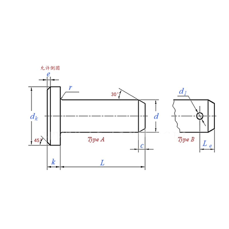
Product Specifications
| Model / Specification | Φ3 - Φ100 |
| Material | Carbon Steel |
| Nom. Dia. d |
Φ3 | Φ4 | Φ5 | Φ6 | Φ8 | Φ10 | Φ12 | Φ14 | Φ16 | Φ18 | Φ20 | Φ22 | Φ24 | |
| d | Max. = Nom. (h11) | 3 | 4 | 5 | 6 | 8 | 10 | 12 | 14 | 16 | 18 | 20 | 22 | 24 |
| Min. | 2.94 | 3.925 | 4.925 | 5.925 | 7.91 | 9.91 | 11.89 | 13.89 | 15.89 | 17.89 | 19.87 | 21.87 | 23.87 | |
| dk | Max. = Nom. (h14) | 5 | 6 | 8 | 10 | 14 | 18 | 20 | 22 | 25 | 28 | 30 | 33 | 36 |
| Min. | 4.7 | 5.7 | 7.64 | 9.64 | 13.57 | 17.57 | 19.48 | 21.48 | 24.48 | 27.48 | 29.48 | 32.38 | 35.38 | |
| d1 | Min. = Nom. (H13) | 0.8 | 1 | 1.2 | 1.6 | 2 | 3.2 | 3.2 | 4 | 4 | 5 | 5 | 5 | 6.3 |
| Max. | 0.94 | 1.14 | 1.34 | 1.74 | 2.14 | 3.38 | 3.38 | 4.18 | 4.18 | 5.18 | 5.18 | 5.18 | 6.52 | |
| c | Max. | 1 | 1 | 2 | 2 | 2 | 2 | 3 | 3 | 3 | 3 | 4 | 4 | 4 |
| e | ≈ | 0.5 | 0.5 | 1 | 1 | 1 | 1 | 1.6 | 1.6 | 1.6 | 1.6 | 2 | 2 | 2 |
| k | Nom. (js14) | 1 | 1 | 1.6 | 2 | 3 | 4 | 4 | 4 | 4.5 | 5 | 5 | 5.5 | 6 |
| Max. | 1.125 | 1.125 | 1.725 | 2.125 | 3.125 | 4.15 | 4.15 | 4.15 | 4.65 | 5.15 | 5.15 | 5.65 | 6.15 | |
| Min. | 0.875 | 0.875 | 1.475 | 1.875 | 2.875 | 3.85 | 3.85 | 3.85 | 4.35 | 4.85 | 4.85 | 5.35 | 5.85 | |
| Le | Min. | 1.6 | 2.2 | 2.9 | 3.2 | 3.5 | 4.5 | 5.5 | 6 | 6 | 7 | 8 | 8 | 9 |
| r | 0.6 | 0.6 | 0.6 | 0.6 | 0.6 | 0.6 | 0.6 | 0.6 | 0.6 | 1 | 1 | 1 | 1 | |
| Wt./1,000 pcs (steel) ≈ kg (A) | - | - | - | - | - | - | - | - | - | - | - | - | - | |
| Wt./1,000 pcs (steel) ≈ kg (B) | - | - | - | - | - | - | - | - | - | - | - | - | - | |
| Nom. Dia. d |
Φ27 | Φ30 | Φ33 | Φ36 | Φ40 | Φ45 | Φ50 | Φ55 | Φ60 | Φ70 | Φ80 | Φ90 | Φ100 | |
| d | Max. = Nom. (h11) | 27 | 30 | 33 | 36 | 40 | 45 | 50 | 55 | 60 | 70 | 80 | 90 | 100 |
| Min. | 26.87 | 29.87 | 32.84 | 35.84 | 39.84 | 44.84 | 49.84 | 54.81 | 59.81 | 69.81 | 79.81 | 89.78 | 99.78 | |
| dk | Max. = Nom. (h14) | 40 | 44 | 47 | 50 | 55 | 60 | 66 | 72 | 78 | 90 | 100 | 110 | 120 |
| Min. | 39.38 | 43.38 | 46.38 | 49.38 | 54.26 | 59.26 | 65.26 | 71.26 | 77.26 | 89.13 | 99.13 | 109.13 | 119.13 | |
| d1 | Min. = Nom. (H13) | 6.3 | 8 | 8 | 8 | 8 | 10 | 10 | 10 | 10 | 13 | 13 | 13 | 13 |
| Max. | 6.52 | 8.22 | 8.22 | 8.22 | 8.22 | 10.22 | 10.22 | 10.22 | 10.22 | 13.27 | 13.27 | 13.27 | 13.27 | |
| c | Max. | 4 | 4 | 4 | 4 | 4 | 4 | 4 | 6 | 6 | 6 | 6 | 6 | 6 |
| e | ≈ | 2 | 2 | 2 | 2 | 2 | 2 | 2 | 3 | 3 | 3 | 3 | 3 | 3 |
| k | Nom. (js14) | 6 | 8 | 8 | 8 | 8 | 9 | 9 | 11 | 12 | 13 | 13 | 13 | 13 |
| Max. | 6.15 | 8.18 | 8.18 | 8.18 | 8.18 | 9.18 | 9.18 | 11.215 | 12.215 | 13.215 | 13.215 | 13.215 | 13.215 | |
| Min. | 5.85 | 7.82 | 7.82 | 7.82 | 7.82 | 8.82 | 8.82 | 10.785 | 11.785 | 12.785 | 12.785 | 12.785 | 12.785 | |
| Le | Min. | 9 | 10 | 10 | 10 | 10 | 12 | 12 | 14 | 14 | 16 | 16 | 16 | 16 |
| r | 1 | 1 | 1 | 1 | 1 | 1 | 1 | 1 | 1 | 1 | 1 | 1 | 1 | |
| Wt./1,000 pcs (steel) ≈ kg (A) | - | - | - | - | - | - | - | - | - | - | - | - | - | |
| Wt./1,000 pcs (steel) ≈ kg (B) | - | - | - | - | - | - | - | - | - | - | - | - | - | |
Pin Shaft Types A and B — Product Introduction
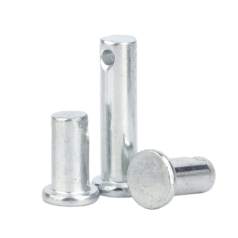
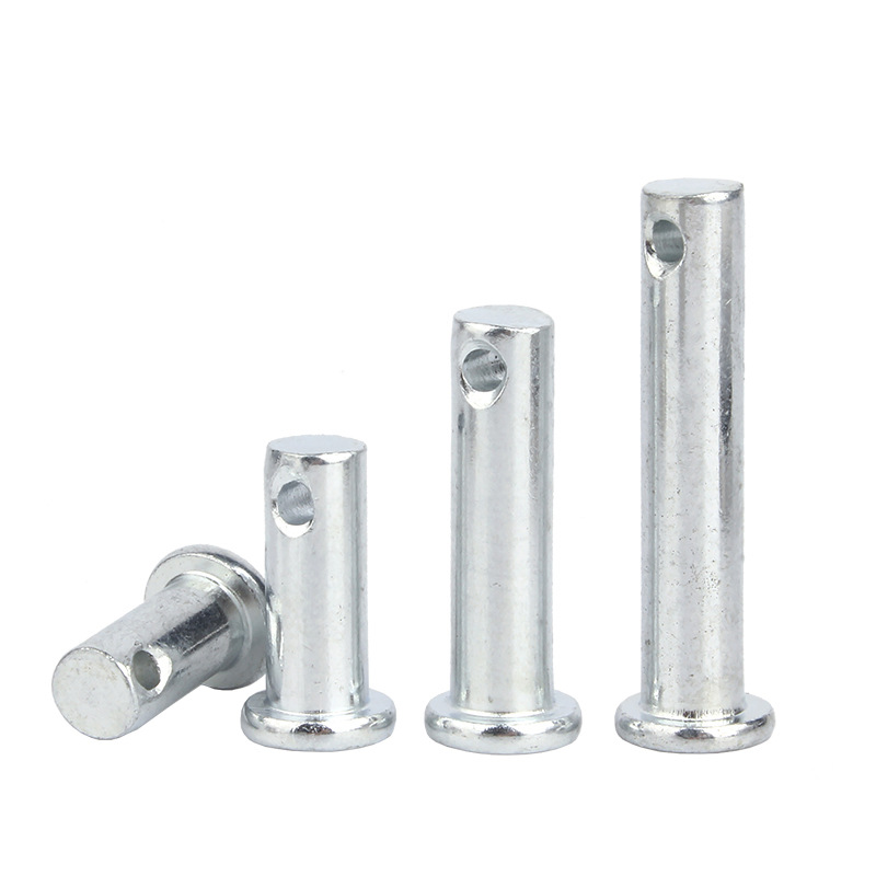
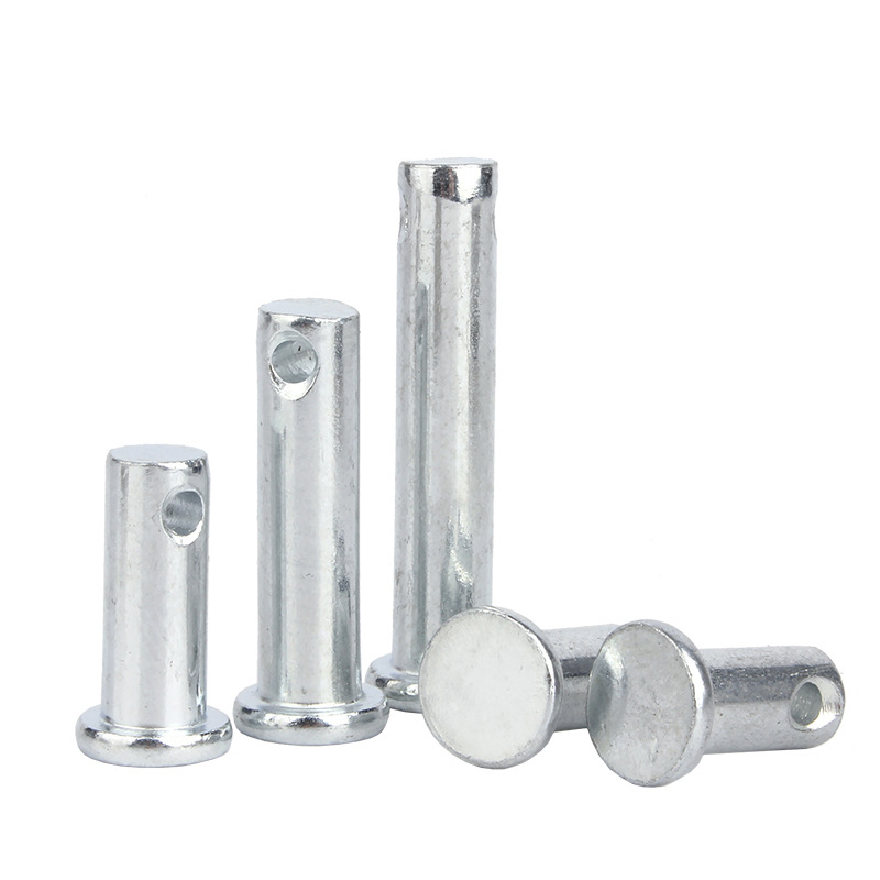
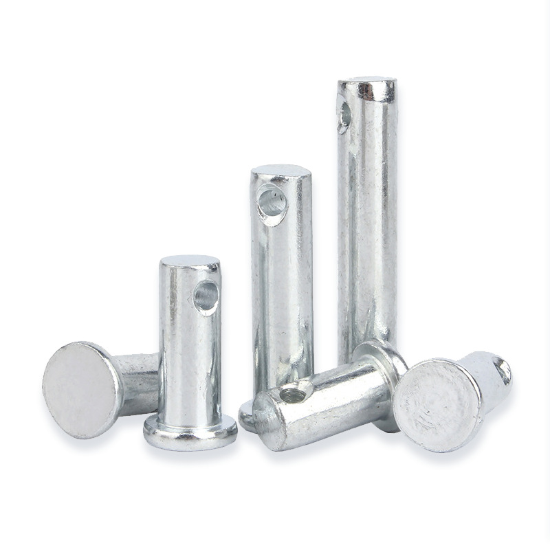
Pin shaft Types A and B are cylindrical hinge fasteners conforming to GB/T 882-2008. They have a round head and an unthreaded shank, and are used to connect two or more parts while allowing relative rotation. According to whether the shank has a split pin hole, the product is divided into Type A and Type B: Type A has no split pin hole (round head design), and Type B has a split pin hole (right-angle design). Nominal diameters cover Φ3 mm–Φ100 mm. Common materials include carbon steel (such as 45 steel, 40Cr) and stainless steel (such as 304).
1. Product Features
• Type A (no split pin hole): Round head, no split pin hole on the shank, relatively simple structure. After installation, it is fixed by the fit between itself and the hole wall. Suitable for static connections or positioning applications with low precision requirements, such as furniture hinges and mechanical positioning.
• Type B (with split pin hole): A split pin hole is provided at the end of the shank, right-angle design. After installation, a split pin can be inserted to form a mechanical stop, effectively preventing the pin shaft from moving axially outward under vibration conditions. Suitable for vibrating environments, such as railway vehicle connections and crane booms.
• Specifications and tolerances: The standard covers nominal diameters Φ3 mm–Φ100 mm, adds 14 specifications including 24 mm–100 mm, and cancels the 25 mm specification; tolerance zone types are expanded to a11, c11 and f8, etc.
• Materials and hardness: The standard does not specify material grades, only material categories and hardness indicators. Common materials include 45 steel, 40Cr alloy steel and stainless steel.
• Special working condition requirements: For applications on railways and where split pins bear alternating transverse forces, it is recommended to use the next larger size split pin and corresponding hole diameter.
2. Product Advantages
• Type A advantages: Simple structure, no additional locking part required after installation, suitable for static positioning connections that do not require frequent disassembly, and relatively low cost.
• Type B advantages: The split pin provides reliable mechanical anti-loosening, effectively preventing the pin shaft from falling out under vibration and alternating load conditions, with higher safety, suitable for key connection parts such as railway and construction machinery.
• Strong versatility: As a national standard product, it has uniform dimensions and good interchangeability, facilitating procurement and maintenance replacement.
• Reliable load capacity: Made of relatively high-strength materials such as 45 steel and 40Cr, it can withstand certain shear and tensile loads.
3. Scope of Application
• Type A: Suitable for static connection applications, such as furniture hinges, mechanical positioning, awning tie rods and similar component connection nodes.
• Type B: Suitable for vibrating environments, such as railway vehicle connections, crane booms, construction machinery hinge points and other locations requiring anti-loosening protection.
• General machinery: Widely used in various mechanical parts requiring hinged connections, such as linkage mechanisms, steering knuckles, lever pivots, etc.